|
Table of Contents
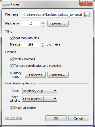
Export meshTo export the map as an optimised mesh file, or a seamlessly tiled set of optimised mesh files, select the 'File→Export→Export optimised mesh' menu option. This will open the export mesh window, shown below:
When this window is opened, you will immediately be asked to provide the mesh file name using a standard Windows file dialog box. Selected areaIf you would like only a selected area of the terrain map to be exported as an optimised mesh, please select the area of the heightfield using the select area tool, or specify the exact coordinates of the selected heightfield area using the 'Edit->Select area' menu option. After you have selected the heightfield area, open the mesh exporter as per normal using the 'File→Export→Export optimised mesh' menu item. File nameYou may type the desired file name of the mesh file into the file name field, or else press the browse button ('…') to select the file name using a standard Windows file window. The list of supported mesh file formats is provided below: Supported file formatsAt the time of writing, the optimised mesh exporter supports the following file formats:
Support for the B3D and TIN mesh file formats will be added as time permits.
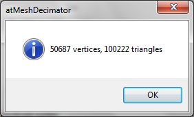
Max. errorYou can control the triangle count of the output mesh using the max. error field. Smaller values produce more detailed meshes with higher triangle counts, whereas larger values produce less detailed meshes with lower triangle counts. Be sure to use the preview button to check the output mesh detail and triangle count. PreviewYou may calculate the mesh triangle and vertex count, and also preview the mesh geometry by pressing the preview button. When you do so, you will be informed of the triangle and vertex count like so:
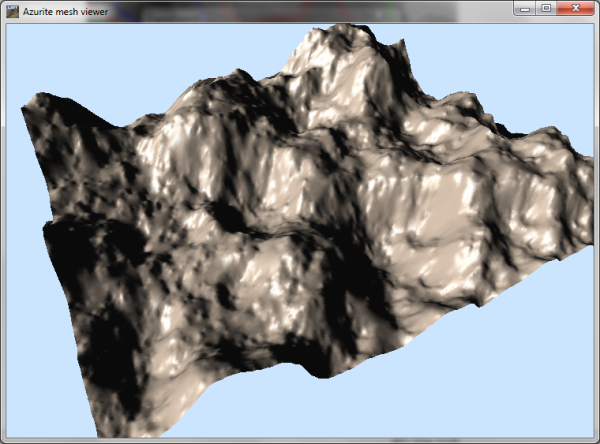
…and then the mesh will be rendered, without materials, like so:
Previewing tiled mapsIf you are using map tiling, the mesh exporter will not preview the entire map, but instead will calculate the triangle/vertex count for the first tile, and show just that tile in the mesh viewer window. TilingIf you would like to export the mesh as a set of seamlessly tiled mesh files, select the split map into tiles checkbox, and set the desired tile size (in heightfield pixels) using the tile size edit control. Tile paddingTo ensure that tiles join up seamlessly, the exporter will automatically include in each tile an additional column and row of vertices from the adjoining tiles. Thus, if you enter a tile size of 256 pixels, the size of each tile may cover 257×257 heightfield pixels, but the start of each tile will be 256 pixels apart. The tile size of texture maps or other auxiliary maps will be calculated to exactly match the corresponding mesh tile area, but may not therefore be equal to a 'nice' number like 512×512 or 1024×1024, etc. Tile order and names
When exporting tiles, the first tile (x=0, y=0) will be saved with the file name value provided in the exporter window, and all other tiles will have '_xayb' appended to their file name (where a and b are the numerical x and y tile coordinates). For example, if you enter the file name as
As per L3DT custom, the tile ordering starts at the south-west (bottom-left hand) corner, with x coordinates increasing to the east and y to the north:
Tile edge optimisationIf the tile size is a multiple of 64 (the patch size of the tessellator), then the edges of the tiles will be optimised just like the rest of the tile. However, if the tile size is not a multiple of 64, the tile edges will be rendered as high-resolution unoptimised triangles. Either way, the geometry of the tile edges will be seamless from one tile to the next.
Optimised tile edges were introduced with L3DT v13.10, and are not available in earlier versions. For more information, please see this blog post.
OptionsVertex normalsIf you select the vertex normals checkbox, the exporter will calculate the normal vectors for each vertex in the mesh and include the normals in the mesh file.
Vertex normals may not be supported by all mesh file formats.
Texture coordinates and materialsIf you select the texture coordinates and materials checkbox, the exporter will generate the texture coordinates and materials for the mesh, and also export the texture image with the mesh. This option is disabled if the texture map has not been calculated.
Texture coordinates and materials may not be supported by all mesh file formats.
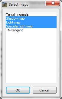
Auxiliary mapsYou may also export other map layers along with your mesh file, such as normal maps, alpha maps, etc. To export these 'auxiliary' map layers, press the auxiliary maps button. This will open a window in which you may select the map layers to be exported:
Notes:
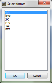
FormatsTo view or change the file formats used to save the texture map and/or auxiliary map layers, press the formats button. If only one image layer is to be exported (i.e. the texture, or one auxiliary layer), this button will directly open the file format selector window:
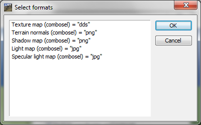
If more than one image layer is to be exported (e.g. texture and alpha maps), you will be presented with the list of maps (shown below). To change the format for each map layer, double-click on the entry in the list. This will open the file format selector window shown above.
Image format optionsThis mesh exporter interface does not yet allow you to edit the settings and options for the image formats, such as compression settings, 'invert axis' options, and the like. You may however edit these options using the 'File→Format preferences..' menu option in L3DT (see user guide). If you require further help in this endeavour, please use the help and support forum. Coordinate systems &cAxesThe mesh exporter currently supports two different coordinate systems; XY plane, Z up and XZ plane, Y up, as explained below. XY plane, Z upThe default coordinate system used by the mesh exporter has the horizontal plane of the terrain being in the X-Y plane, with X to the east, Y north, and Z up. To use this coordinate system, select the XY plane, Z up option in the axes drop-list.
The 'XY plane, Z up' is the default coordinate system used by L3DT, OpenGL and Blender.
XZ plane, Y upAn alternative coordinate system supported by the exporter has the horizontal plane of the terrain being in the X-Z plane, with X to the east, Z north, and Y up. To use this coordinate system, select the XZ plane, Y up option in the axes drop-list.
The 'XZ plane, Y up' is the default coordinate system used by DirectX.
Face windingThe mesh exporter supports both face winding conventions:
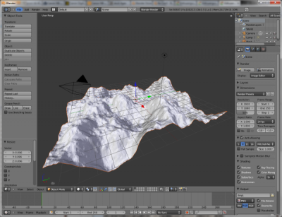
Origin at centreIf you would like the origin of the map (i.e. where the x=0,y=0 coordinates are located) to be in the centre of the mesh, select the origin at centre checkbox. This will ensure the mesh is centred when loaded in 3rd party applications like Blender:
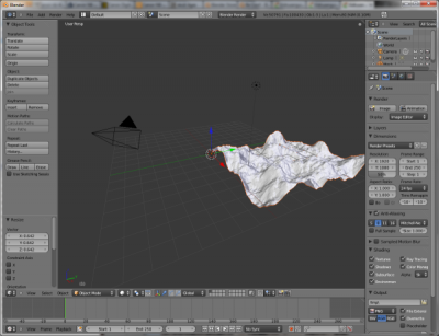
If you leave the origin at centre checkbox un-checked, the origin will be left at the L3DT default, which is the south-west (bottom-left hand) corner of the map:
Example coordinate system settingsExporting DAE files for BlenderTo export DAE (COLLADA) files for Blender, select the following coordinate system options:
Exporting OBJ files for BlenderTo export OBJ files for Blender, select the following coordinate system options:
When importing the OBJ file into Blender, sure to disable the '-X90' checkbox in the Blender OBJ importer, as shown below:
If you do not disable the '-X90' checkbox, the OBJ import script in Blender will rotate the map axes as if the map was saved in the 'XZ plane, Y up' coordinate system, with the result that the map will appear to stand up on its side. This is obviously undesirable. Exporting X files for Direct3DTo export X files for Direct3D, select the following coordinate system options:
Before you click OKBefore you click OK, be sure to press the preview button to check on the output triangle/vertex count and the detail of the output mesh. It will save you time and effort if you catch incorrect settings in the mesh exporter rather than some time down the track in your game engine, mesh renderer, or whatever. After you click OKWhen you click OK, the mesh exporter will begin cutting the map into tiles (if you've enabled tiling), exporting texture maps (if texture coordinates and materials are enabled), exporting auxiliary maps (if enabled), and generating and saving decimated mesh files. At the time of writing, this process will spawn multiple progress bars, and ultimately conclude without showing any message. If an error occurs in the export, you will be notified. Example outputAn example of the output of the optimised mesh exporter is shown below, wherein a 1024×1024 pixel heightmap and 4096×4096 pixel texture map were split into a 4×4 array of mesh tiles, which were then imported one by one into Sapphire to show the seamless tiling.
Except where otherwise noted, content on this wiki is licensed under the following license:CC Attribution-Share Alike 3.0 Unported
|

